

Control Panels and Turnout Wiring
Return to main page
Return to Tips and Techniques
You can click on any picture to see a larger version.
The Jersey Subdivision is built using Tortoise stall controllers. Each Tortoise is wired using Cat5 cable and all Cat5 cables are brought back to 66 punch down blocks.
Cat 5 cables are also wired to the control panels and punched down to the respective Tortoise connections.
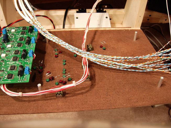
On the back of the control panels the PS4 circuit breakers from Tony's are mounted on 1.5" standoffs. This gives clearance to the LEDs and switches mounted on the front of the control panel. On the DCC panel I also mounted the DS64s on a piece of 1/8" hardboard also on standoffs.

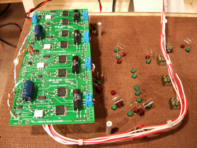
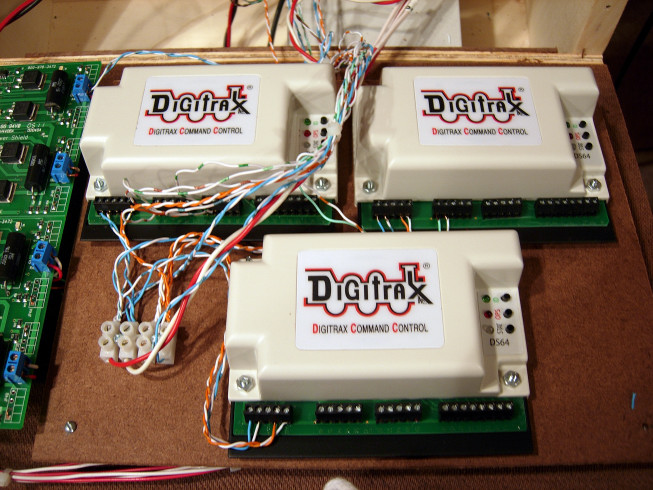
The Cat 5 cables to the panel are then wired to the LEDs and DS64s.

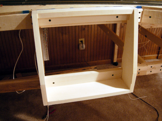
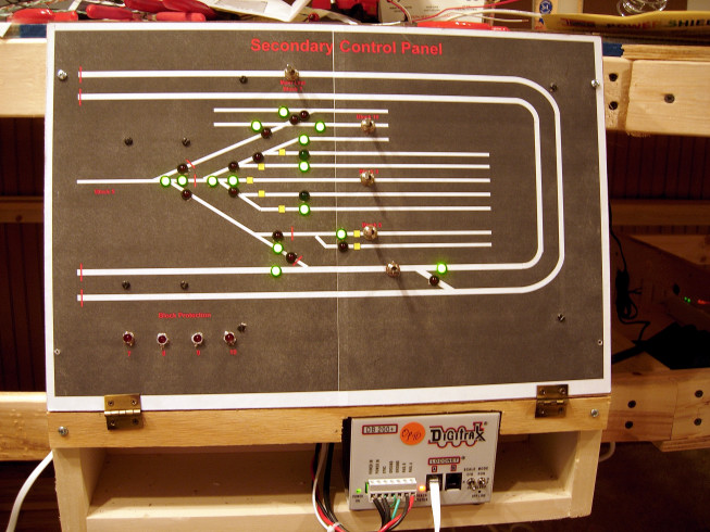
The panel itself is 1/8" hardboard mounted on a frame. The hardboard is covered with the panel template diagram. I create these using a CAD program and I print then across 2 sheets of Avery Label 8.5"x11" paper. This creates a panel that is 11"x17". Since labels are self-adhesive, the key is to line them up before pressing them to the hardboard. A new template can always be printed and applied over the existing template. Green LEDs represent a closed turnout. Red LEDs represent a thrown turnout., The yellow squares denote where uncoupling magnets are located.

Lastly, since I used DCC controls for the second half of the layout, I created a cheat sheet to remember the routes and switch numbers.
