
Layout lighting DCC Decoder Adapter
Return to main page
Return to Tips and Techniques
What is the Decoder Adapter ?
I wanted a solution which would provide multiple DC outputs that could be controlled from my DCC throttle and didn't draw power from the track. The High Current Decoder Adapter has four DC outputs. The first is a fixed 12V DC output for control panels, switch machines and similar. Two outputs are a 12V DC off/on switched output which is controlled independently by F0 and F1. The fourth is a variable 0-12V DC output which is controlled by the throttle setting. The Decoder Adapter is powered by a standard DCC mobile decoder. I chose the Digitrax DH163P decoder but any similar decoder will work. You control it just like a normal locomotive.
What's New ?
6/5/2008 Version 1.5 of the high current decoder adapter has been released. It contains a couple of minor changes. Various values of R5 have been provided so that you can select your minimum and maximum fixed / switched voltage ranges. The voltage control input to Q1 was moved from the wipe of R4 to the top and the wiper connected to the top. This provides for slightly better voltage regulation, since the resistance between the Q1 output and control input will remain fixed.
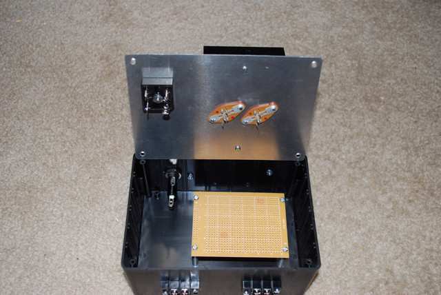
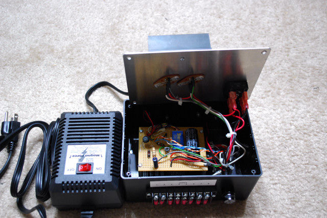
Some pictures of the construction process of my unit.
2/3/2008 Click here for a schematic of a high current version with two switched output zones. This version can scale up to 10A and more of output current. The base schematic uses the popular Magna Force MF615 power supply but any 15-20 VDC or 12-18 VAC supply can be used. Note that if the source does not provide current limiting, I highly recommend adding a fuse of sufficient size to protect the source. Also F1 is shown as a 2A fuse. It can safely be scaled up to 5A as long as the source can provide enough current. Make sure that Q1 and Q2 have an adequate size heat sink. On this version you can also adjust the output voltage for the fixed and switched outputs. Adjust R4 for the proper output voltage. I use 14V Minatronics bulbs for my layout and adjust this to 13V. The part numbers are all for Radio Shack or Jameco Electronics.
10/25/2007 Version 3 of the Decoder Adapter has one minor change, the additional of R2. By adding R2 and adjusting the decoders motor control via speed tables you will be able to get a very smooth brightness increase with the throttle. Without R2 the decoder adapter will tend to light brightly at low throttle settings. R2 smoothes out the response curve.
Shared 12v DC Click to enlarge diagrams Discrete 12v DC


8/19/2007 Version 2 of the Decoder Adapter has a number of improvements. The prior version would only work when the direction control was set the proper direction. The new version is direction independent and has much better isolation between the decoder and the Decoder Adapter circuitry. This will save on potentially fried decoders. The variable delay has been fixed by reducing the size of C3.
Shared 12v DC Click to enlarge diagrams Discrete 12v DC


Version 2 detailed changes
Bidirectional support - D3/D4 were added to allow both the forward or reverse lighting outputs (Yellow/White) to power the RY1 relay, which switches on/off the switched DC output. The cathodes of both diodes face the Yellow/White leads because Digitrax uses a positive common output on the blue lead. The inline diode D2 was replaced with a full wave bridge rectifier. This allows the motor lead outputs (Orange/Gray) of the decoder to be in either polarity/direction and still maintain the correct polarity to the base of Q2. The value of R1 was reduced to compensate for a slightly reduced Vmax due to the voltage drop of the bridge rectifier. D2, as a bridge rectifier, provides much better electrical isolation between the decoder and the Decoder Adapter circuitry.
Reduced Delay - The value of C3 was reduced from 220uf to 47uf. This, along with the reduced value of R1, significantly reduced the charge/discharge time of C3. This makes the Decoder Adapter much more responsive and removes almost any noticeable delay.
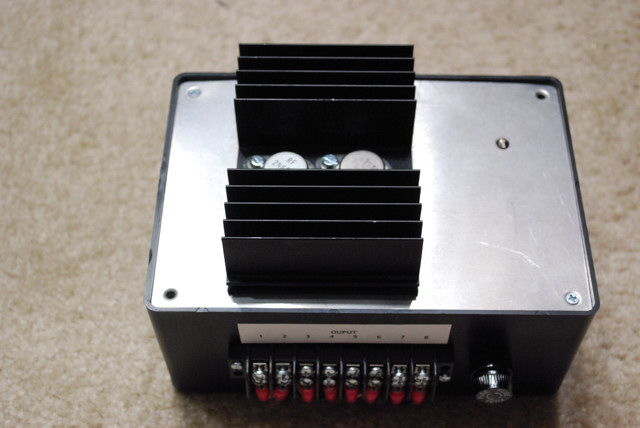
Operation is as simple as selecting the decoder address. The on/off output (TB1-3 and TB1-4) are selected by the F0 function. Once you have selected the decoder address you can adjust the brightness output by simply increasing the throttle. The output for TB1-5 and TB1-6 will vary between 0 and 11 volts. The constant 12v DC outputs can power control panels, switch machines and other 12v DC devices.
Note - Once you have the decoder programmed properly, I recommend setting the decoder lock feature via CV16. This will keep you from accidentally resetting the decoder ID or other variables. This would then require you to move the inputs to reprogram the decoder. Locking the decoder will prevent thsi from happening. This is the voice of experience talking.
Here are some pictures of my built unit. (click to enlarge)


There are many options and modifications you can make to the base design. It can be modified to use an external transformer, modified to increase the power output, modified to adjust the fixed 12v outputs to higher voltages and more.
Feel free to provide feedback or write if you have questions. I can be reached at jeff@thebinks.com .
Important Note Important Note Important Note
The above schematics and designs are presented "as built". You are free to use at your own risk. I do not provide any warranty, guarantees or assume any liability for the reliability, usage, accuracy or any other aspect of this information. If you choose to build this device you assume all risks to persons, your layout and any other damage, either directly or indirectly that may occur. You are free to modify any or all portions of this design but again, you assume all risks.