
Layout lighting Decoder Adapter
Return to main page
Return to Tips and Techniques
All current updates are posted here.
8/19/2007 A new version of the Decoder Adapter is available. It is highly recommended that you do not use the version on this page and instead use the updated version. It contains a number of improvements.
7/26/2006 During construction of the Jersey Subdivision the electrical crew decided they wanted to have layout lighting but they wanted to be able to turn on/off some lights and others they wanted to be able to adjust the brightness. They also wanted all of it to be controlled via DCC but not steal power from the trails to power the lighting. They looked at all options and decided to design a DCC decoder adapter. Two different designs were created.
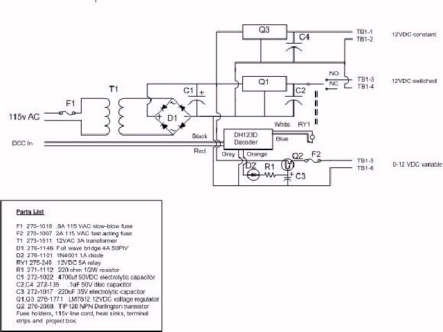
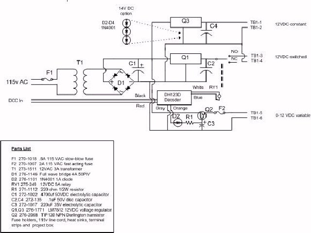
Shared 12v DC Click to enlarge diagrams Discrete 12v DC
The difference between the two is the discrete 12v DC has a separate 12V 1amp voltage regulator for each output. The adapter is designed around Digitrax HO scale decoders but may work with others. Hookup is as simple as connecting the DCC In connections to the track to receive decoder signals. You can connect it to the mainline, since the mainline will likely always be powered. Note that you must first use a programming track to program the decoder. At minimum you need to program a decoder address.
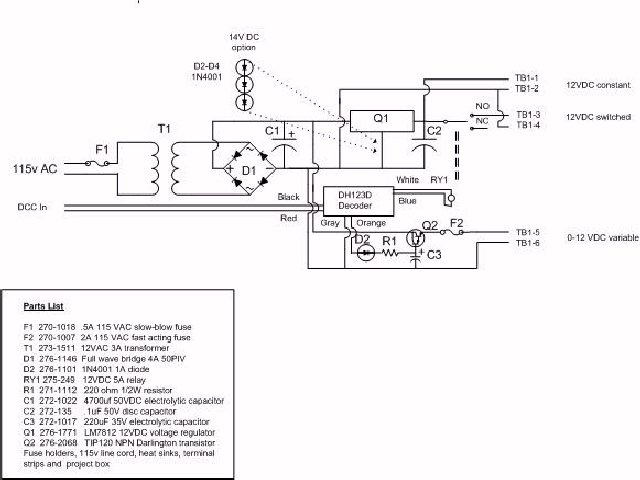
If you need a fixed voltage higher than 12v DC, you can adjust it by adding diodes in series for the ground lead of the voltage regulator. Here is a 14V option. I went with this due to some of the Minatronics lighting which had 16V grain-of-wheat bulbs. Each diode adds about .6V DC to the output.
Operation is as simple as selecting the decoder. The on/off output (TB1-3 and TB1-4) are selected by the F0 function. Note that the locomotive must be set in the forward direction. If you want the on/off to work whether the decoder is set in the forward or backwards direction, the a full wave bridge rectifier will need to be added on the blue/white F0 decoder outputs and before RY1 (relay 1). Once you have selected the decoder address you can adjust the brightness output by simply increasing the throttle. The output for TB1-5 and TB1-6 will vary between 0 and 14 volts. If you want to limit it to 0-12 volts, then add a 12v 1w Zener diode in parallel to C3. The constant 12v DC outputs can power control panels, switch machines and other 12v DC devices.
Here are some pictures of my built unit. (click to enlarge)


There are many options and modifications you can make to the base design. It can be modified to use an external transformer, modified to increase the power output, modified to adjust the fixed 12v outputs to higher voltages and more.
Feel free to provide feedback or write if you have questions. I can be reached at jeff@thebinks.com .
Important Note Important Note Important Note
The above schematics and designs are presented "as built". You are free to use at your own risk. I do not provide any warranty, guarantees or assume any liability for the reliability, usage, accuracy or any other aspect of this information. If you choose to build this device you assume all risks to persons, your layout and any other damage, either directly or indirectly that may occur. You are free to modify any or all portions of this design but again, you assume all risks.